Quantcast
Channel: Cadence Custom IC Design Blogs
Viewing all 827 articles
Browse latest View live

The Leader of the Orchestra: Getting Started with Virtuoso ADE Verifier

$
0
0

The members of an orchestra are often great virtuosi on their own instruments, but the conductor - the maestro – is equally important. The maestro has his score on the conductor’s stand to know exactly what is supposed to be played. He explores the individual intonation and assembles the orchestra into a unique sound. Most importantly, he has to verify that every single tone fits the master plan – the score of the musical composition. 


Virtuoso ADE Verifier

There is a third product besides Virtuoso ADE Explorer and Virtuoso ADE Assembler in the new ADE tool group – Virtuoso ADE Verifier. Let’s check out what it is good for and how to get started quickly – in fact in 3 minutes to make it a bit of a challenge!

You may have seen the introduction material on ’The New Sound of Analog Design’. There is more material to help you get started (links below), if you happen to have more than 3 minutes. 


Verifier in 3 Minutes

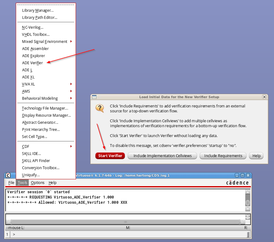
Open Virtuoso IC6.1.7 in your current working area. Go to ‘Tools / ADE Verifier’ from the CIW to launch the new verification tool. You can skip over the initial dialog by clicking ‘Start Verifier’. Et voilà – Verifier is up. 

Start Verifier

Now we should enter our verification requirements – but let’s skip that and instead work bottom-up! Find the ‘Add…’ button located at the bottom of the ‘Implementations’ panel. Browse and select a suitable ADE or a new ‘maestro’ cellview if you have one. If you pick an ADE state, Verifier will automatically convert it into a new ‘maestro’ cellview. What is ‘suitable’? Well, select something small with a few measurements and spec for now. 

Verifier Mapping

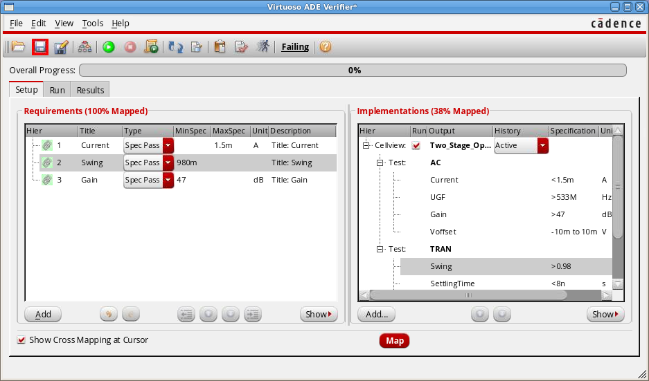
In the ‘Implementations’ panel, multi-select everything you find important, click the right mouse button, and select ‘Create Requirements’. Two things happen now: (1) new requirements are created from the selected implementations, and (2) the new requirements are mapped to their corresponding implementations. Hover your mouse over some implementations or requirements – do you see the mapping?

The structure and content of our verification plan isn’t great but we have to compromise for our ‘3 minute goal’. I’m sure you will find out how to add new entries to the plan, change the hierarchy, and edit the description of the entries.


1 Minute Remaining!

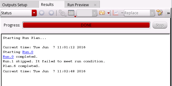
Move over to the ‘Run’ tab and click the green run button. Now, Explorer/Assembler will be running in the background and hopefully give you a nice ‘Run Finished’ feedback soon. Spend 10 seconds to review the right-hand side information on the ‘Run’ tab before you move over to the ‘Results’ tab. 

Verifier Run Tab

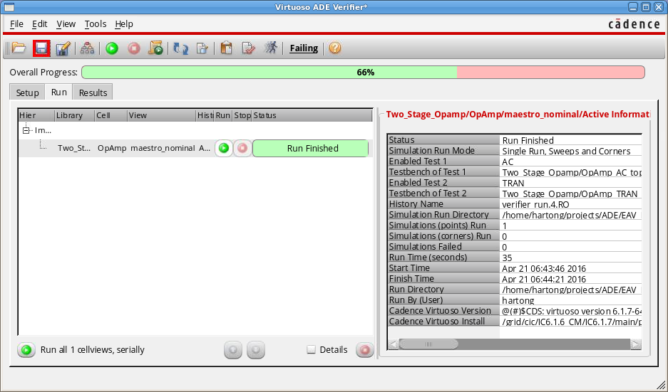
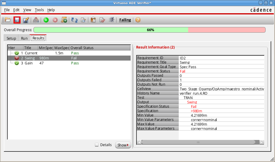
Here you should see your requirements with the pass/fail status attached to it. Spend another 10 seconds to review the right-hand side again. Save your new Verifier cellview for later.

… And – time over 2:59 – great job!!!

Verifier Results


So what?

Have you gained any additional design/verification information in these 3 minutes? Probably not, but remember the orchestra. Hiring a conductor for your harmonica playing at home would be pretty silly, wouldn’t it? But think if you could get an overview of all your simulation results for the current project. Now assume you could have an overview of the results of the whole team and finally assume you have a precise verification plan telling you exactly what you need to do, what you have done already and what is missing. Wouldn’t this make you the maestro of your own analog verification project?

Did you make this journey in 3 minutes? Drop us a comment below. Your questions and ideas are welcome too.

TeamADE


More Info

For more details, take a look at the following videos and material:

Whitepaper:

Videos:


Virtuoso Video Diary: Flexible Connectivity Support of Dummy Devices

$
0
0

Virtuoso Video Diary is envisaged to be an online journal that will relay information about Virtuoso videos that are available in the Cadence Online Support Video Library. For IC6.1.7 and ICADV12.2, over a hundred videos on a wide variety of new and exciting Virtuoso features have already been created. Virtuoso Video Diary brings you direct links to these videos and other related material, on regular basis, in your mailbox. You can subscribenow to receive the e-mail notifications.

Why am I talking about dummies?

If I were to tell you that at lower geometries, Dummy Instances can guard active instances against process variations and from interference due to surrounding instances and nets, your response might be, “Don't talk history".

That dummy devices—dummy resistors and capacitors—can help maintain transistor performance at lower geometries, is not new. But do you know that dummy instances, which are passive devices because they have all their instance terminals connected to the same net, can be abutted to active instances, to free up some space in the layout. Some respite. At small geometries, accommodating additional dummy instances could be a bit too much to ask for.

Layout XL makes abutting dummy instances child’s play. Drag–drop, Drag-drop, and you can see the terminals of the dummy instance change their connectivity with each new drop that results in a valid overlap. Click the Play button below for a brief preview of the functionality.

(Please visit the site to view this video)

If you have already used Layout XL to create dummy instances, tied them to a power or ground net, abutted them to an active instance, and know how the dummy instances change their connectivity with each overlap; then the full video, that I wanted to introduce to you, has nothing new to offer.

But, if anything here does sound new, or interesting, you might want to view the full video.

Click the video link now OR visit Cadence Online Support and search under Resources — Video Library for the video titled Demonstrating Flexible Connectivity Support of Dummy Instances

Note:Cadence Help supports native playback of videos (mp4) added to the installed Virtuoso Documentation Library. Look under Video Demos for a video topic of your interest. 

Related Resources

Virtuoso Video Diary  – What’s Next

Virtuoso Video Diary will next bring to you an interesting video titled Markers: Tips and Tricks’ This video demonstrates the various tips, tricks, and shortcuts that you can apply while working with markers in Virtuoso Visualization and Analysis XL. Stay tuned…


Rishu Misri Jaggi

Virtuoso Video Diary: Tips and Tricks on Virtuoso Visualization and Analysis XL Markers

$
0
0

Virtuoso Video Diary is envisaged to be an online journal that will relay information about Virtuoso videos that are available in the Cadence Online Support Video Library. For IC6.1.7 and ICADV12.2, over 100 videos on a wide variety of new and exciting Virtuoso features have already been created. Virtuoso Video Diary brings you direct links to these videos and other related material, on a regular basis, in your mailbox. You can subscribe now to receive the e-mail notifications.

The Story of Virtuoso Visualization and Analysis XL Markers 

Have you explored the various types of markers offered by Virtuoso Visualization and Analysis XL? If not yet, then probably it’s time. Markers are one of the useful features of Virtuoso Visualization and Analysis XL graphs and can help you perform efficient graph analysis.

Consider a scenario where you have a myriad of traces plotted in a graph. Somebody tells you to analyze the graph behavior at specific points on a trace or combination of traces, or find out the delta values between two or more points for one or more traces. Yes, all these tasks seem difficult to perform at first glance! In fact, these cases cause a void that can be filled by an easy-to-use, robust, and powerful feature available within the graph.

The good news is that such a feature exists. Use different types of markers!

The Basic Question: What are Markers?

A marker is basically a label used to attach a description to a point on the trace, and by default displays the X and Y coordinates of its intersection with the trace. With the help of markers, you can view and analyze the specific points or areas on the trace and perform further analysis. You can also use the markers to represent expressions. Markers can be of various types, such as point, vertical, horizontal, AB, delta, and so on. Let us have a quick look at the picture below to get an idea of how markers look. In this picture, the trace contains the point (M1), vertical (V1), and horizontal (H1) markers.  


You can use the Markers menu any time to create and work with markers. Here are some useful tips, tricks, and shortcuts that you can use and apply to make the tasks faster and improve the productivity.

Moving Ahead: Some Useful Shortcuts

  • Bindkeys

I always find it convenient to use keyboard shortcuts, typically termed as bindkeys in Virtuoso language, to create and work with markers. Sometimes using menu options to perform these operations could turn into a wearisome task.

I'm sure you would like them, too. Here is a list of some useful bindkeys that you can keep handy:

    • M, V, H: Creates a point, vertical, and horizontal marker, respectively.
    • Q: Opens the marker properties form that you can use to change the various attributes of a marker, such as label, position, intercepts, significant digits, notation, and so on.
    • N, P: Moves the marker to next or previous points on the trace based on the snapping criteria selected in the Next/Prev Snap Point drop-down available in the marker properties form. The default snapping criteria is Data Point. The other available options are—Local Maxima, Local Minima, Local Max or Min, Specific Y Value, Specific X Value, Global Maxima, and Global Minima. I must say it’s really an interesting and useful feature and comes handy when you want to analyze specific values on the trace.
    • Shift+D: Creates a delta marker between two or more markers: It’s interesting to note that you can mix point, vertical, horizontal marker and get delta values from a point to a line.
    • D: Creates a chain of delta markers. Select a marker and wherever on the trace you press the bindkey D, you will get a marker of the selected type and a delta value between them.
    • Ctrl+E:  Deletes all the markers at one go. It acts like a savior when you have lots of markers added on the graph. Moreover, if you have delta markers added on to the graph, you can hide their child labels to make the graphs look neat. 
  • Drag-and-Drop

Well, it is not a new feature for graphs, but a very convenient one! It’s helpful when you want to instantly view the marker intercept values at different locations on the trace. Undoubtedly, you can also change the intercept values through the marker Properties form, but you need to perform a series of steps to do that.

  • Context-Sensitive Menu

Right-click a marker and use the context-sensitive menu options to perform certain marker-specific tasks, such as change the marker properties, snap the marker to the next or previous edge, delete the marker, and so on.

  • Horizontal and Vertical Marker Tables

Use these assistants to view the intercept values of all the horizontal or vertical markers added on to the graph. To open these assistants, choose WindowAssistantsVert Marker Table or Horiz Marker Table. Alternatively, right-click anywhere on the menu bar and open these assistants from the context-sensitive menu. The one thing I like about these assistants is they act as 'one-stop shop.'

  •  Special Marker (AB)

We call it an AB Marker! This is a special delta marker of type XY and helps view the dx, dy, and slope values between two points on the same or different traces. Note that a graph can contain only one AB marker. To create another pair, you need to convert the AB marker into a normal delta marker.

To explain these shortcuts even better and in an elaborate way, we have a ‘Tips and Tricks: Markers’ video available on Cadence Online Support. Click the Play button below to watch a brief snippet of this video. 

(Please visit the site to view this video)

If you find the feature interesting and worthwhile, you might want to learn more about it. We recommend you to watch the full video to get a complete picture. Click the video link now OR visit Cadence Online Support and search under Resources — Video Library for the video titled Tips and Tricks: Markers.

Note: Cadence Help supports native playback of videos (mp4) added to the installed Virtuoso Documentation Library. Look under Video Demos for a video topic of your interest. 

Related Resources

Virtuoso Video Diary: What's Next

Virtuoso Video Diary will next bring to you an interesting video titled Introducing the Redesigned Virtuoso Forms. The video showcases the redesigned forms across Virtuoso applications. You will notice that the redesigned forms are easy to use, consistent, and visually appealing. Stay tuned…

Ashu Vashishtha

Analog Design Resonance: When a Plan Comes Together

$
0
0

Yes, indeed, we all love it when a plan comes together. A plan for running all the simulations you need, using different combinations of tests, corners, variables, and run modes. A plan that you can execute with a single button before you go home in the evening. A plan that will stop if, for some reason, your design isn't performing to spec so that you aren't wasting resources running simulations on a bad design. The Run Plan Assistant in Virtuoso ADE Assembler is designed to do all this and more.

What Is a Run Plan?

  • A Run Plan is a sequence of runs created from different variants of the active Assembler setup.
  • The execution of each run can depend on pass/fail conditions occurring in other runs.
  • Scripts can be inserted before and after each run to perform user-specified actions and pass results from one run to another.
  • Run Plans can be executed either from the UI in the Run Plan Assistant, or written out as a script to run in batch mode from the command line.

Getting Started

Open the Run Plan Assistant using the Create->Run Plan banner menu in ADE Assembler. The easiest way to get started is to use the first icon "Create New Run from Active Setup". This adds an entry in the assistant containing what you have currently defined in your Assembler setup. Now you can modify that information in the Run Plan Assistant to do things such as enabling/disabling tests and corners, changing the run mode (for example, from "Single Run, Sweeps, and Corners" to "Monte Carlo Sampling"), and modifying variable and parameter values. Changes you make here do not affect the active setup. Be aware, however, that changes you make in Assembler to the test setup itself (analysis options, simulator settings, outputs, specifications) will be used wherever that test is enabled in the Run Plan. The Run Plan is not a copy of the active setup. Think of it as a set of pointers with the ability to override certain elements.

You can repeatedly use the "Create New Run from Active Setup" button to add runs into the Run Plan, modifying the settings for each one. If you need to run some tests over corners and other tests with Monte Carlo, it's easy now.

Conditions and Dependencies

One of the most powerful capabilities of Run Plans is the ability to create conditions on each run that must be met in order for the run to start. Do this by clicking the right mouse button on a run and selecting "Edit Run Conditions". Here you can set up conditions for a run based on successful simulation completion, specifications passing, and/or yield thresholds.

On this Run Conditions form, you can also provide Skill scripts which can be executed before or after each run. In this way, you can, for example, grab a measured value from one run and use it to set the value of a variable in a subsequent run. The new mae* API functions (more on that in another post) make it easy to access setup and results from the maestro database.

Ready, Set, Go!

Run Plans can be executed using the "Execute Plan" button in the Run Plan Assistant, or you can use the "Save Script" icon to save a script, which you can use to execute the Run Plan from the command line. If you have a distributed job policy (and who doesn't?), all the runs within the Run Plan will fire off in parallel, unless, of course, you have created dependencies and conditions, in which case we will sort those out and stage the simulations accordingly.

While the simulations are running, the display will switch to the Status tab, which has been enhanced to provide a nice summary of the Run Plan progress, including hyperlinks to open the results from the individual runs.

More Information

Virtuoso Video Diary: Redesigned Virtuoso Forms

$
0
0

Enhanced User Experience with Redesigned Virtuoso Forms

Research and customer feedback has revealed that you feel some Virtuoso forms are quite complex, with too many options displayed on the forms and use models that are unclear. Based on your feedback, we have begun redesigning the most frequently used forms across Virtuoso applications.

As you start to use the redesigned forms in Virtuoso, you will see that they are easy to use, consistent, and visually appealing. The new forms use progressive disclosures, which enable you to show or hide additional fields on forms. Some forms use tree views which let you select an option in the navigation pane to view the related fields. Another interesting feature provided in some forms is the Search field, which lets you quickly find fields on forms where the number of options simply cannot be reduced. To make the interface simple, some forms now have a vertically arranged collection of tabs that lets you show or hide information about a specific category.

There are already around 25 redesigned forms in Virtuoso Layout Suite, Virtuoso Schematic Editor, Virtuoso Space-based Router, Virtuoso ADE Verifier, and Translators and more are planned for upcoming releases. The video excerpt below provides a flavor of the changes that have been made.

(Please visit the site to view this video)

You can view the full video that introduces the redesigned Virtuoso forms. Click the video link now or Visit Cadence Online Support and search under Resources — Video Library for the video titled Introducing the Redesigned Virtuoso Forms.

Note: Cadence Help supports native playback of videos (mp4) added to the installed Virtuoso Documentation Library. Look under Video Demos for a video topic of your interest.

Related Resources

For a full list of all redesigned forms, check the What's New documentation for your product, or refer to the user guides listed below.

Virtuoso Video Diary  – What’s Next

Virtuoso Video Diary will next bring to you a set of videos on the new Virtuoso ADE product suite, which includes ADE Explorer, ADE Assembler, and ADE Verifier. These next-generation ADE products provide you an improved experience to explore, analyze, and verify your analog and mixed-signal designs against your design goals. The related videos have been designed to provide a quick overview of these products and their key features so that you can get started with them. Stay tuned…

About Virtuoso Video Diary

Virtuoso Video Diary is an online journal that relays information about Virtuoso videos that are available in the Cadence Online Support Video Library. For IC6.1.7 and ICADV12.2, over a hundred videos on a wide variety of new and exciting Virtuoso features have already been created. Virtuoso Video Diaries brings you direct links to these videos and other related material, on regular basis, in your mailbox. Subscribe to receive the e-mail notifications.

Waveform Thumbnails

$
0
0

Wouldn't it be great if you could see your plots directly on the schematic? Well in ADE Explorer, now you can!

Run a simulation in Explorer and open the design in tab and choose Waveforms from the show/hide balloon drop down or use the bind key CTRL+B

Hover over the nets/terminals in the design and balloons showing the simulation plot will appear.

To pin the balloons use the bindkey SHIFT+B or click on the pin icon on the upper right hand corner of the balloon.

You can zoom in, out and fit using the buttons on the balloon, the RMB context menu and the bindkeys [ ] f

Plots can also be sent to ViVA using the RMB context menu if you wish to carry out a more detailed analysis.

Viewing Plots from Different Analyses

The balloons show the plots for one analysis at a time, to toggle between different analyses simply change the analysis drop down and all pinned or new balloons will now show the selected analysis. If you want to prevent a balloon from toggling analysis then RMB on the balloon and choose Freeze Analysis.
.

Appending Waveforms & Legends

Changing the plot mode to append means that any new simulations will append the plots to the pinned balloons. By default a maximum of 4 plots will be appended, after that the oldest plot is overwritten.  The legend will show the combinations of variables used in the simulation for each plot.  Selecting a combination of values in the legend drop down will cross select the plot in ViVA too.

The colors will dim in the same shade of color by default, the boldest plot and the top in the drop down list is the newest.

Sweeps & Corners

Variable sweeps & corners will be shown in different colors and again you can cross select from the legend to ViVA.

Clearing Waveform Thumbnails

If you want  to clear your waveform thumbnails simply use the Clear Waveform Balloons icon.

Waveform Thumbnail Settings

The waveform thumbnails have been optimized to be as small as required so as not to obscure too much of the canvas - you can easily drag them to resize. However if you want to change the settings of the waveform thumbnails open the Balloon Options form using the toolbar icon and adjust the size, position and pause/fade time there.

Here's a handy hint - if you want to see the axes by default in the balloons then change the Max Height to 198 and Max Width to 205

Waveform Thumbnail Video

Click here for a short video to see these waveform thumbnails in action!

IEEE Recognition of Cadence Software at DAC 2016

$
0
0

Cadence was awarded with the IEEE Donald O. Pederson Best Paper Award—EDA’s most prestigious recognition of its kind—for the best paper published in IEEE Transactions on CAD over the past two years. 

The paper, “Fast Statistical Analysis of Rare Circuit Failure Events via Scaled-Sigma Sampling for High-Dimensional Variation Space”, was part of a collaboration with Carnegie Mellon University. The award itself recognizes the best paper that has been published over the past two years based upon general quality, originality and subject matter.  The paper describes a new algorithm to calculate the rare failure rate with consideration of variability and uncertainties in manufacturing process, allowing companies to validate their integrated circuits with significantly less simulation time.

The algorithm is part of the Virtuoso Variation Option and is available today.  The feature, named Scaled-Sigma Sampling, is very simple to use.  You can learn more about the technology by reading the blog overview, by consulting Cadence documentation or have a chat with your field support representative to schedule a demonstration.

Virtuoso Variation Option: Reliable High Yield Design with Scaled-Sigma Sampling

$
0
0

What’s Scaled-Sigma Sampling?

Scaled-Sigma Sampling (SSS) is an efficient algorithm to solve the high yield estimation problem, which happens when your circuit needs to have really low failure rate, like one in a million or one in a billion. This can be because you are designing a high repetitive circuit like memory cell or flip-flop, or you are an automotive or medical designer who just wants to be very conservative. The problem is well known for its difficulty – millions or billions of Monte Carlo samples traditionally need to be simulated to get a meaningful number of failures to estimate the yield.

 SSS is motivated by a simple observation: if the variation of all variables is scaled up by a factor of s, we would observe much more failures to easily estimate the yield. It is further proved that under very general assumptions on the failure region, the failure rate P can be modeled by this simple yet elegant equation:

 So we only need to perform Monte Carlo sampling at a few larger scaling factors, which is efficiently handled within our spectre simulator. Once we compute the model coefficients (α, β, γ) from the simulation results, the model will give us a yield estimate and provide a confidence interval for that estimate.

Why use Scaled-Sigma Sampling?

So there’s some cool math here, but there are so many high yield estimation tools, why do I want to use SSS? It turns out SSS is able to efficiently solve many difficult problems that most other tools are having trouble to handle:

  • High dimensionality: If your circuit size is large, there could be many underlying variables used to model variation. Most other algorithms perform much more simulations in that case, but SSS does not. Dimension information in SSS is encoded into the three model coefficients.
  • High Nonlinearity: It doesn’t matter if you have a strongly non-Gaussian distribution, or you have multiple failure regions. SSS can solve them all!
  • Large Number of Specs: If you have many specification targets and want to estimate the yield for all of them, most other algorithms perform much more simulations to sequentially work on one spec at a time, but SSS does not. The yield of all specs are simultaneously estimated in parallel.
  • Very High Yield: Many other algorithms have difficulties when yield is very large (>= 6sigma). SSS has no difficulty handling any large yield.

How to use Scaled-Sigma Sampling within the Cadence environment

It’s really simple to run the SSS algorithm when you have the Virtuoso Variation Option.  From either the Virtuoso ADE Explorer or Assembler, open the Monte Carlo setup form. Then just select “Create statistical corners” as the task, specify your yield target for your design (at least 4 sigma, or one in 32K), then click OK and run. That’s it!


If you are an advanced user, here are a few more things you can consider:

  1. SSS can be run by choosing the task as either “Verify the yield (sign-off)” or “Create statistical corners”. The difference is that the latter will automatically create corners according to your yield requirement at the end of the run. These corners can be used for you to efficiently perform design iterations without having to repeatedly run SSS. The corner creation process does not run extra simulations so the overhead is typically not significant.

2. The default number of samples for SSS is 7000, which is an empirical number we found to be adequate for most designs. You can modify this number depending on your simulation budget and/or accuracy requirement.


After SSS finishes, ADE will show the yield both in sigma and percentage. If some specs have extremely high yield, it will show a yield lower bound:


More information can be found in the run log, including the confidence interval and functional yield estimation. Functional yield means the yield if only errors are counted as failures. This is useful for some circuits for which we want to know whether it works but there’s no hard threshold on performance.

Final Words

Scaled-Sigma Sampling within the Cadence environment is very simple and reliable. Just push a few buttons and it will get the job done. You don’t have to worry whether your problem is too hard. You don’t have to worry if it will take forever to finish, because you know in advance it’s just a few thousand simulations and it’s highly parallelizable. If you haven’t tried it yet, try it now!

More Information

Scaled-Sigma Sampling Paper

High Sigma Statistical Analysis Virtuoso Variation Option Rapid Adoption Kit

For more details on how Virtuoso Variation Option can efficiently help you create a variation-aware design, take a look at our white paper:

Accelerating Monte Carlo Analysis at Advanced Nodes


Adding Weighted Noise Via Calculator Custom Function

$
0
0

Applying a weighting factor to a Noise Summary run requires lots of steps and the results cannot be evaluated without using the form. Wouldn't it be much easier if you could have a calculator function to do this?

You can create a custom function in the calculator that uses the script attached, weightedTotalNoise.il, simplifying this flow.

Traditional Flow

In order to apply a weighting factor to a Noise Summary you need to

  • Run a noise simulation
  • Choose Results->Print->Noise Summary
  • Specify the location of the weight file

Once you apply or OK the form, the Noise Summary is printed in the Results Display Window.


Using a custom function to apply the weighting


In the calculator click the Add template icon to add the custom function

Specify the path to the weightedTotalNoise.il file and Create New


Choose the weightedTotalNoise function and fill in the form, you can press preview to see what the function will look like in the calculator.


Once you have clicked OK the new function is shown in the Custom Function section of the Calculator Function Panel.
All custom functions are in Blue making them easier to find.


You can select the function and fill in the arguments


Evaluate the function and you get the following result. This is the same as the value you get using the Noise summary form above.


The expression can be sent back to Virtuoso Analog Design Environment (ADE) outputs and will be automatically evaluated at the end of the simulation.

This custom function will be saved and will be available in your future Virtuoso ADE sessions

Generic Custom Functions

You can add a custom function for any SKILL script following the same steps.

Virtuoso Video Diary: Getting Started with the New ADE Product Suite

$
0
0

Hey, did you hear the buzz around the new Virtuoso ADE product suite, which was introduced in IC6.1.7? The products in this suite—Virtuoso ADE Explorer, Virtuoso ADE Assembler, and Virtuoso ADE Verifier—have made a good start, just as we expected!

The new single-test simulation environment, Virtuoso ADE Explorer, provides some really exciting features. Our favorite ones are real-time tuning with Spectre, waveform balloons on schematic, and an integrated graph assistant. Built-in corners and Monte Carlo statistical analysis provide the capability to perform advanced performance analysis of a single block. It’s also interesting to note that if you own a Virtuoso Variation Option (VVO) license, you can access the advanced Monte Carlo features from within Virtuoso ADE Explorer. An artistically-designed, user-friendly interface makes all the features more usable and easy to access. Experience it yourself!

After exploring your design in Virtuoso ADE Explorer, turn to the multi-test environment, Virtuoso ADE Assembler. Not only it is an extension of Virtuoso ADE Explorer to simulate multiple tests together, it also offers some extra features, such as availability of advanced run modes—Global and Local Optimization, Monte Carlo, Worst Case Corners, and Sensitivity Analysis—to meet the advanced simulation needs. Similar to Virtuoso ADE Explorer, you can add a VVO license to run advanced Monte Carlo features as well as verify the yield and get clues on improving it. Another exciting feature worth exploring is the Run Plan assistant. You can use it to plan the simulation runs and set up regressions by creating multiple variations of the setup within a single session. If you ever wished to run simulations where each test has its own run mode, its own set of corners, or where simulation runs could depend on the completion status of other runs, try it now!

And finally, Virtuoso ADE Verifier, which we are sure is going to be liked by those who are interested in monitoring the progress of the complete analog design. It provides a comprehensive infrastructure for an overall verification of all the pieces of the design together. After testing, analyzing, and fine-tuning the various blocks individually using Virtuoso ADE Explorer and Virtuoso ADE Assembler, you can use Virtuoso ADE Verifier to see how the results of each unit are mapped to the highest level circuit specifications.

Although each tool has its own bunch of features, it is interesting to see how intelligently and effortlessly they all are tied together with a common database consisting of maestro cell views. If you haven’t got a chance to try out the tools yet, watch these videos on Cadence Online Support for a quick overview:

Related Resources

Virtuoso Video Diary: What's Next

Virtuoso Video Diary will next bring to you a video that introduces WSP Manager and shows you how to use this new form to create and edit width spacing patterns (WSPs), copy WSPs from another design, and generate WSPs from existing shapes in the layout. WSPs are used in advanced-node designs for correct-by-construction track-based routing. Stay tuned…

Ashu Vashishtha, Deepti Mishra Gupta, Namrata Malhotra

About Virtuoso Video Diary

Virtuoso Video Diary is an online journal that relays information about Virtuoso videos that are available in the Cadence Online Support Video Library. For IC6.1.7 and ICADV12.2, over a hundred videos on a wide variety of new and exciting Virtuoso features have already been created. Virtuoso Video Diaries brings you direct links to these videos and other related material, on regular basis, in your mailbox. Subscribe to receive the e-mail notifications.

Virtuoso Variation Option: Reliable High-Yield Design with Scaled-Sigma Sampling

$
0
0

What’s Scaled-Sigma Sampling?

Scaled-sigma sampling (SSS) is an efficient algorithm to solve the high-yield estimation problem, which happens when your circuit needs to have a really low failure rate, like one in a million or one in a billion. This can be because you are designing a highly repetitive circuit like a memory cell or flip-flop, or you are an automotive or medical designer who just wants to be very conservative. The problem is well known for its difficulty – millions or billions of Monte Carlo samples traditionally need to be simulated to get a meaningful number of failures to estimate the yield.


SSS is motivated by a simple observation: if the variation of all variables is scaled up by a factor of s, we would observe many more failures to easily estimate the yield. It is further proved that under very general assumptions on the failure region, the failure rate P can be modeled by this simple yet elegant equation:

So we only need to perform Monte Carlo sampling at a few larger scaling factors, which is efficiently handled within our Spectre® simulator. Once we compute the model coefficients (α, β, γ) from the simulation results, the model will give us a yield estimate and provide a confidence interval for that estimate.

Why Use Scaled-Sigma Sampling?

So there’s some cool math here, but there are so many high-yield estimation tools. Why would I want to use SSS? It turns out SSS is able to efficiently solve many difficult problems that most other tools are having trouble handling:


  • High dimensionality: If your circuit size is large, there could be many underlying variables used to model variation. Most other algorithms perform many more simulations in that case, but SSS does not. Dimension information in SSS is encoded into the three model coefficients.
  • High non-linearity: It doesn’t matter if you have a strongly non-Gaussian distribution, or you have multiple failure regions. SSS can solve them all!
  • Large number of specs: If you have many specification targets and want to estimate the yield for all of them, most other algorithms perform many more simulations to sequentially work on one spec at a time, but SSS does not. The yield of all specs are simultaneously estimated in parallel.
  • Very high yield: Many other algorithms have difficulties when yield is very large (>= 6sigma). SSS has no difficulty handling any large yield.

How to Use Scaled-Sigma Sampling Within the Cadence Environment

It’s really simple to run the SSS algorithm when you have the Virtuoso Variation Option.  From either the Virtuoso ADE Explorer or Assembler, open the Monte Carlo setup form. Then just select “Create statistical corners” as the task, specify your yield target for your design (at least 4 sigma, or one in 32K), click OK, and run. That’s it!


If you are an advanced user, here are a few more things you can consider:

  1. SSS can be run by choosing the task as either “Verify the yield (signoff)” or “Create statistical corners.” The difference is that the latter will automatically create corners according to your yield requirement at the end of the run. These corners can be used for you to efficiently perform design iterations without having to repeatedly run SSS. The corner creation process does not run extra simulations, so the overhead is typically not significant.

2. The default number of samples for SSS is 7000, which is an empirical number we found to be adequate for most designs. You can modify this number depending on your simulation budget and/or accuracy requirement.


After SSS finishes, ADE will show the yield both in sigma and percentage. If some specs have extremely high yield, it will show a yield lower bound:


More information can be found in the run log, including the confidence interval and functional yield estimation. Functional yield means the yield if only errors are counted as failures. This is useful for some circuits for which we want to know whether it works but there’s no hard threshold on performance.


Final Words

Scaled-sigma sampling within the Cadence environment is very simple and reliable. Just push a few buttons and it will get the job done. You don’t have to worry about whether your problem is too hard. You don’t have to worry if it will take forever to finish, because you know in advance it’s just a few thousand simulations and it’s highly parallelizable. If you haven’t tried it yet, try it now!

More Information


Scaled-Sigma Sampling Paper

High Sigma Statistical Analysis Virtuoso Variation Option Rapid Adoption Kit


For more details on how Virtuoso Variation Option can efficiently help you create a variation-aware design, take a look at our white paper:

Accelerating Monte Carlo Analysis at Advanced Nodes


Team ADE 

Analog Design Resonance: Quick and Efficient Regression Scripts–Now Possible with ADE Explorer and ADE Assembler

$
0
0

You must have experienced and appreciated the new Virtuoso ADE product suite that is packaged with a lot of easy-to-use, productivity-enhancing, and robust features. Did you notice the tools also offer a new set of SKILL functions? Let’s learn about these functions. 

The new functions can be used with both Virtuoso ADE Explorer and Virtuoso ADE Assembler, and provide ease and efficiency in setting up regression flows from batch mode. These functions can be used only for the maestro cellviews, thus their names are prefixed with mae. You can have a quick look at the list of available functions in Cadence SKILL API Finder.

Note: To open the Cadence SKILL API Finder window, click Tools -> Finder in the CIW.

Let’s look at some of the benefits that these new functions provide.

Ease of Use

The mae functions are comprehensive, that is, each function takes care of most of the required elements itself. Thus, you can complete an action by using fewer commands as compared to an ADE XL script. In addition, the new functions always work in context of the current session and setup database, so you don't need to provide these values as arguments unless you are working with multiple sessions. This makes scripting much simpler!

For example, if you need to load a maestro cellview, enable a test or a set of corners, run simulation, and save results, you can do this by using a just few commands, as shown below.


session=maeLoadSetup("myLib" "myCell" "myView" ?mode "a")
; loads the active setup for the given cellview
maeSetSetup(?test '("test1") ?enabled t)
; enables test 'test1'
maeSetSetup(?corners '("corner1" "corner2") ?enabled t)
; enables two corners
historyName=maeRunSimulation()
maeExportOutputView(?fileName "simResults.csv" ?view "Detail")
; exports the simulation results to a csv file
exit()

Compatibility with the Existing SKILL Functions Used for ADE L and ADE XL

There are mae functions for most of the common actions, but if there is any specific action for which an mae function is not available, you can use the existing axl or asi functions. For example, to find the parasitic run mode set in the given session, you can use the axlGetParasiticRunMode function and provide the setup database for the maestro session as an argument to that.

Similarly, you can edit the model file for a test using the handle to the maestro test in the asiAddModelLibSelection function, as shown below.


sess=maeLoadSetup("opamp090" "full_diff_opamp_AC" "maestro" ?mode "a")
=> "fnxSession0"

Example 1:
handleSDB=axlGetMainSetupDB(sess)
=> 1001
axlGetParasiticRunMode(handleSDB)
=> "No Parasitics/LDE"

Example 2:
testnames=maeGetSetup()
=> ("AC" "TRAN")
testHandle=maeGetTestSession(car(testnames))
=>stdobj@0x21989b60
asiAddModelLibSelection( testHandle "../models/spectre/gpdk090.scs" "NN" )
=> t 

Ability to Save Scripts Directly from the User Interface

Another interesting feature is that if you have configured the setup, including the tests, outputs, run options, etc., in the Virtuoso ADE Explorer or Virtuoso ADE Assembler user interface, then you can save that in a script by running the maeWriteScript command from the CIW. Yes, that's a quick way to create a script, but that's not all! There's an additional benefit—since the saved script uses a reference to the cellview, if you make any change in the cellview later, the script will always be synchronized with it. No need to update the script to reflect the changes in the setup. Now, doesn't that sound useful?

More Info

For more details about these functions, refer to the following collateral:

TeamADE

High-Sigma Showdown: Which Method is Better?

$
0
0

The adoption and usage of advanced node technology (16nm and below) has been extraordinary over the last few years. However, along with the benefits in power and area, the new nodes also contain new challenges when it comes to properly determining the variation caused by the smaller geometries.  Much has been written about the proper ways to physically implement a FinFET design, but less has been written on the need for accurate variation analysis using some sort of statistical sampling. For most of these applications, due to the fact that they are usually designs that must meet their targets past the traditional 3-sigma boundaries, standard Monte Carlo simulations would take far too long to be able to provide accurate results.  So, new mathematical methods have emerged to help solve this problem.  The two competing methods are High-Sigma Monte Carlo (HSMC) and Scaled-Sigma Sampling (SSS) which is the preferred method used by Cadence’s Virtuoso suite of tools.

The accuracy of the HSMC method strongly depends on the accuracy of the underlying response surface model, which is created first and then used to select the Monte Carlo samples to be simulated. If the response surface model is biased, the wrong samples could get selected for simulation and the results could be completely biased. The initial response surface model is built using a very limited number of samples out of hundreds of millions or even billions of possible samples. In most cases, these initial samples come from the area encompassing the normal working condition of the design. We have found that the circuit behavior can be quite different around the mean as compared to the tail conditions. The response surface model bias may indicate a wrong tail region for subsequent sampling, causing significant inaccuracy.

Scaled-Sigma Sampling generates a reasonably large number of samples in the actual failure region without making assumptions.  These more predictive samples are then used to estimate the failure rate.  By combining this sampling method with Cadence’s Spectre circuit simulator, we are able to provide an additional performance boost since the random number generation is efficiently handled within Spectre instead of having to be provided outside of simulator and then restarting the simulator with new values.

We believe as a user, you will find that SSS method has the advantage over HSMC if one or more of the following conditions apply:

High Dimensionality:  The number of simulations does not increase with circuit size for Scaled-Sigma Sampling. For HSMC, the number of samples to build response surface model and the cost of handling a large number of parameters will significantly increase with number of devices.

High Nonlinearity:  The SSS method is proven to work particularly well with strongly nonlinear problems because of its very general assumptions. For HSMC, it is extremely difficult to build a response surface model when an output is a very complicated nonlinear function subject to a large number of statistical variables.

Large Number of Specifications: For the SSS method, the number of simulations does not increase with number of specs. This is not the case for HSMC.  Having a large number of specifications that need to be tested can overwhelm the HSMC method.

Very High Yield:  The SSS method has no difficulty handling arbitrarily large yield, including >= 6 sigma. For HSMC the problem of handling huge amounts of data becomes very difficult when the yield is near 6 sigma. For example, for a billion MC samples with 1000 variables, and each variable requires 8 bytes to store as a double value, the total amount of data is 8TB, which is beyond the capacity of a typical computer’s memory or even disk. Any operations with this large amounts of data will take significant time and hurt the program’s overall runtime.

TeamADE is pleased to offer our customers a more detailed whitepaper on this topic that can be downloaded from here.  We are also honored to include the world’s largest foundry endorsement of our technology.  You can see the webinar here to understand more about the value they see in our methodology.  This technology is available as either part of the Virtuoso Analog Design Environment GXL or with the Virtuoso Variation Option.

If you are interested in more details about what Cadence can do for you in providing a comprehensive design flow for designing, implementing and verifying advanced node designs, please visit us at:  Cadence Advanced Node Design Solution

Virtuoso Video Diary: Introducing WSP Manager

$
0
0

Are you an advanced node layout or CAD engineer trying to find a methodology for routing designs in the Virtuoso platform? Interested to learn how to specify tracks for correct-by-construction designs using width spacing patterns (WSPs)? If you are not using the WSP Manager in the Virtuoso environment to create and modify your WSPs, now is the time to try it.

Using Width Spacing Patterns for Advanced Node Designs

Advanced node design demands extensive additional design rules. Width spacing patterns are used to maintain those rules and define tracks with specific widths and spacing for interactive placement and routing. Previously, you defined WSPs in the foundry’s technology file or using SKILL.

WSP Manager was introduced in ICADV12.2 ISR5 as a convenient GUI for creating and modifying WSPs. You can also preview WSPs to visualize exactly how they would appear in your layout, before saving them to your design database. You can share WSPs amongst your team by importing WSPs from a common cellview. If your design has placed instances and objects, you can easily generate a WSP grid from those shapes. To find out how to use WSP Manager, watch these videos on Cadence Online Support:

Note: Cadence Help supports native playback of videos (mp4) added to the installed Virtuoso Documentation Library. Look under Video Demos for a video topic of your interest.

Related Resources

What's Next

Virtuoso Video Diary will next bring to you a set of videos on the SKILL IDE performance analysis tools that include Code Browser, Lint Manager, and Profiler. These tools help you assess the performance of your SKILL code and identify any areas of improvement. The related videos demonstrate the key features of these tools that can help you refine your SKILL code. Stay tuned…            

About Virtuoso Video Diary

Virtuoso Video Diary is envisaged to be an online journal that will relay information about Virtuoso videos that are available in the Cadence Online Support Video Library. For IC6.1.7 and ICADV12.2, over a hundred videos on a wide variety of new and exciting Virtuoso features have already been created. Virtuoso Video Diaries brings you direct links to these videos and other related material, on regular basis, in your mailbox. Subscribe to receive the e-mail notifications.

Analog Design Resonance: Playing with Filters

$
0
0

We'd like to welcome guest writer Yanyan Qiao from our Cadence Japan AE team.  Many thanks for her contribution!

Today analog design has become very challenging. Analog circuit designers need tools which can provide deep insight into circuit behavior. The MMSIM simulator family provides device check functions, as well as static circuit topology checks and dynamic behavior check functions for typical design problem verification. Virtuoso Analog Design Environment (ADE) is capable of generating these check statements which are applied during simulation and collecting the output results to give a detailed graphic interpretation.

Before IC_6.1.7, Virtuoso ADE supported a post-processing GUI function for device checks (assert statements): Violation Display. Users could access a text report table of “Violations Summary” and “Violation Detail” which are collected from simulation output. The “Highlight” button under the “Violations Summary” table helped to locate the device in the design for which the specific violation was reported.

In IC_6.1.7, Violation Display has been replaced by a more powerful and comprehensive GUI function: Results-Checks/Asserts View. The new function is available in Virtuoso ADE XL, ADE Explorer, and ADE Assembler. It not only supports device checks, but also static and dynamic checks. It is an easy-to-use filter function to sort out violation reports as required by the user. Hyperlinks are embedded in the table to provide handy access to desired details: waveforms of selected violation items, detailed explanation, related device or node location in design, etc.

Designers who are used to applying hundreds/thousands of check statements can get great benefit from the new filter function:

1)  Results-Checks/Asserts View is a text report table with the top row serving as a simple data filter. It works just like the data filter of Excel; users can select any item from the pull-down list. Filtered results can be further refined by other data filters or “Violation Filter” function stated later.

For example, users can select dyn_highz check from the top data filter of the “Type” column, then apply a user-defined (customized) filter of specified start time on previous filtered results.

2)  Table contents can also be controlled by “Violation Filter,” which is above the right-hand side of the table. By default, filters are listed for each type of check statement available from simulation results. 

3)  Users can create their own filter rules using simple logic expressions noted in the linked manual below; wild cards are supported. User-customized filters will be shown in the Violation Filter list for selection.

Query Operators for custom filters

For example, users can make a simple filter if they are interested in multiple check statements.

4)  The Violation Filter list is also available in the “violations” type outputs setup. Users can select from the list to display information in the traditional Results->Detail view.


Please enjoy the new function and feel free to share your experience. 

Team ADE


Virtuoso Video Diary: SKILL IDE Performance Analysis Tools

$
0
0

As a SKILL code developer, do you spend a major chunk of your time in fine-tuning your SKILL code? I am sure nobody writes perfect code in the first attempt. Producing efficient and bug-free code involves several iterations of proactively monitoring the code, eliminating bottlenecks, and analyzing as well as improving its performance. And there are tools that can help you improve your code’s performance without affecting its behavior.

Hey, don’t panic! I am not asking you to learn any new tools. Everything you need for improving the performance of your SKILL code is available within Cadence SKILL IDE. We don’t call it an ‘Integrated Development Environment’ for no reason!

SKILL IDE offers the following three tools to help you find what ails your code:

  • SKILL Code Browser

Code Browser is a source code navigation and analysis tool, which allows you to browse your code without having to keep track of the declarations and references of each program element. It is designed to enhance your ability to understand and modify your SKILL programs. Using the Code Browser, you can view the call graph of user-defined functions. You can also jump directly to the definition of the function selected in the Code Browser window. In short, Code Browser helps you keep an eye on your code without overly complicating things.

  • SKILL Lint

SKILL Lint can be used for statically checking SKILL and SKILL++ programs for possible errors and inefficiencies that may go undetected during normal testing. SKILL Lint also provides hints about improving the efficiency of your code. So, like a good friend, SKILL Lint points out the issues in your code and gives you hints on fixing them.

  • SKILL Profiler

SKILL Profiler is a performance analysis tool that provides information about the run-time behavior of your code. Using the Profiler, you can identify the functions that are consuming the most time or memory during a run. You can then evaluate these functions for possible performance improvements. In short, SKILL Profiler keeps the guesswork out of performance analysis.

Watch the following videos on Cadence Online Support:

NoteCadence Help supports native playback of videos (mp4) added to the installed Virtuoso Documentation Library. Look under Video Demos for a video topic of your interest. 


Related Resources

  • Cadence SKILL IDE User Guide 

What's Next

Virtuoso Video Diary will next bring to you a set of videos on Symbolic Placement of Devices (SPD), a row-based symbolic placer that lets layout engineers perform quick and easy placement of PMOS and NMOS devices. These videos will help you get started with using SPD and understand some of its prominent features, such as smart move, multirow placement, signal trunks, and user-defined abutments. Stay tuned…

About Virtuoso Video Diary

Virtuoso Video Diary is envisaged to be an online journal that will relay information about Virtuoso videos that are available in the Cadence Online Support Video Library. For IC6.1.7 and ICADV12.2, over a hundred videos on a wide variety of new and exciting Virtuoso features have already been created. Virtuoso Video Diaries brings you direct links to these videos and other related material, on regular basis, in your mailbox. Subscribe to receive the e-mail notifications. 

Virtuoso Video Diary: SPD – A Symbolic Way to Edit Your Physical Design

$
0
0


The best way to complete a complex task is to break it into smaller, simpler tasks.

This is exactly what Symbolic Placement of Devices, popularly known as SPD, does for layout engineers. SPD is a symbolic row-based placer. Designed primarily for small to medium-sized designs, SPD displays only the relevant information needed to perform device placement. Using SPD layout, engineers can easily edit device placement, preview the updated designs, and finally, generate the layout.

Why Do I Need a Tool Like SPD?

The design rules for real devices are constantly increasing. As a result, the amount of computation needed to perform any task, starting from Pcell evaluation right through to device placement, has also increased by many times.

Several applications perform complicated post-processing tasks to get a DRC error-free design. SPD helps you avoid most of these additional tasks and heavy computation during editing. Complexity comes into picture only when you preview the design. This is when the tool converts symbolic devices to real devices.

Row-based Placement

The prime focus of SPD is to improve productivity of layout designers by facilitating quick and easy placement of PMOS and NMOS devices. By default, the symbolic layout arranges devices in an NP row pattern. The top row (P row) of the design, represented in red, contains the PMOS devices and the bottom row (N row), represented in green, contains the NMOS devices. SPD supports several row patterns that you can use to optimize your design.

Row-based Placement in Symbolic Placement of Devices


The Benefits

Among the several benefits of SPD, the top three are:

  • Symbolic - Symbolically represented devices, with neatly drawn orthogonal flight lines, minus any complex data, are easy to understand. Editing placement of these devices is a lot simpler than real devices.
  • Simplicity - The simple use model of the SPD commands enables device placement in just a few mouse clicks
  • Speed - Editing in SPD is much faster than editing real devices on the main layout canvas

Getting Started with SPD

To get you started with SPD and help you learn more about the tool, we have created a few videos to demonstrate its various features:

Click the video link now OR visit Cadence Online Support and search under Resources — Video Library for the video title.

Note: Cadence Help supports native playback of videos (mp4) added to the installed Virtuoso Documentation Library. Look under Video Demos for a video topic of your interest.

Getting Started with Symbolic Placement of Devices

This video demonstrates the complete SPD flow. It also shows how to use some of the main commands, such as smart move, abut, and generating chained devices.

 SPD Flow

Performing Multi-row Placement in SPD

SPD supports several row patterns, such as NP, PN, NPPN, PNNP, NPNP, PNPN, NNPP, PPNN, NNNP, PNNN, NPPP, PPPN, NNNN, and PPPP. The video shows how using multiple row patterns in SPD helps in optimizing a design.

 Multirow Placement in Symbolic Placement of Devices

Creating Signal Trunks in SPD for Pin-to-Trunk Routing

Flight lines in the symbolic design can be converted to signal trunks. These trunks can be directly used for pin-to-trunk routing in layout. The combined flow can provide up to 10X productivity gain. Check out the video to see how to create signal trunks in SPD and then use them for pin-to-trunk routing in Virtuoso Layout Suite XL.

 Creating Signal Trunks in SPD

Using User-Defined Abutment and Callback Functions

In advanced node designs, to perform PDK-specific abutments, such as dummy poly abutment, you might need to define your own custom abutment callback functions. You can enable user-defined abutment in SPD by loading the callback functions and registering them before launching SPD. Otherwise, only the default oxide diffusion abutment will take place.

SPD also supports the user flow callback functions that further help in customizing the design in specific steps of the SPD flow. Although particularly useful at advanced nodes, the user flow callback functions are also supported in mature node versions.

The video demonstrates the SPD flow when you have defined the user-defined abutment and user flow callback functions.

Related Resources

NoteFor more information on Cadence products and services, visit www.cadence.com.

What's Next

Virtuoso Video Diary will next bring to you a video on the Net Class Group and Net Class Hier Group constraint types that are available in the Constraint Manager assistant. You can use these constraint types to group multiple routing-related constraint types. The Net Class Hier Group constraint type also allows you to define spacing between each member. The related video demonstrates the process of using these constraints types. Stay tuned…

About Virtuoso Video Diary

Virtuoso Video Diary is an online journal that relays information about Virtuoso videos that are available in the Cadence Online Support Video Library. For IC6.1.7 and ICADV12.2, over 100 videos on a wide variety of new and exciting Virtuoso features have already been created. Virtuoso Video Diary brings you direct links to these videos and other related material, on regular basis, in your mailbox. Subscribe to receive the e-mail notifications.

Virtuoso Video Diary: Creating Net Groups and Constraining Them with Spacing Using Net Class Hier Group Constraint

$
0
0

 In this new age of complex designs and scaling of technology nodes, there are more number of wires per given square unit of area. As a result, applying constraints is considered wise to make sure signal integrity (SI) is taken care off well. It is due to this reason that circuit designers show a growing preference for using a larger number of constrained and managed nets. These constrained nets, if possible, can be used as it is or in a group with another set of constrained nets to define spacing with respect to another group or individual constrained nets. At this moment, have you ever thought that if the Constraint Manager assistant could offer this ability, your life as a circuit designer would be simplified and you would be able to face the challenge of tracking and handling such constraints in the design better?

Well, keeping this requirement in mind, the Constraint Manager assistant now provides two new constraint types, Net Class Group and Net Class Hier Group. Both these constraint types allow you to group one or more members belonging to the following routing-related constraint types: Diff Pair, Bus, Matched Length, Net Class, and Symmetry. A Net Class Hier Group constraint also allows you to do the following:

  • Include Net Class Group constraints as a member.
  • Create constraint directly on the constrained nets without a need to have groups.
  • Define spacing to space out the constraint members at equal distance.

Using these constraints is extremely easy! Just select the required constraint types in the Constraint Browser and choose Net Class Group or Net Class Hier Group from the Constraint Creation–> Routing menu.

If a Net Class Group or Net Class Hier Group constraint already exists in the Constraint Browser, a simple drag and drop of a specific constraint type on it can help you to add a new constraint member. Guess what, you can add any number of members that you want to a Net Class Hier Group constraint and it will equally space out all its members. However, while adding new members, consistency checks will be performed to avoid spacing-related conflicts between the members of the Net Class Hier Group constraint especially when it contains a Net Class Group constraint.

The video excerpt below shows an example of creating a Net Class Hier Group constraint.

(Please visit the site to view this video)

You can view a full video on grouping and spacing out constraint members using a Net Class Hier Group constraint. Click the video link now or visit Cadence Online Support and search under Resources — Video Library for the video titled Creating Net Class Hier Group Constraints.

Note: If you don’t have a Cadence Online Support account, you can play the Creating Net Class Hier Group Constraints video (mp4) natively in Cadence Help when you are using Virtuoso IC6.1.7/ ICADV12.2 (ISR6 or later). In the Cadence Help Virtuoso Documentation Library, look under Video Demos for each of the videos in the series.

Related Resources

Note: For more information on Cadence products and services, visitwww.cadence.com.

Virtuoso Video Diary  – What’s Next

Virtuoso Video Diary will next bring to you a video series titled - Staying XL-Compliant by Manipulating the Layout Hierarchy - that explains how it can sometimes help to take the unconventional route of desynchronizing the schematic and layout hierarchies, and still say Layout XL-compliant. This is possible with the enhanced Make Cell and Flatten commands, when used in Layout XL. Stay tuned to learn what being desynchronized, yet Layout XL-compliant means, what makes this possible, what are the situations to benefit from this, and finally, how does one make it happen… 

About Virtuoso Video Diary

Virtuoso Video Diary is an online journal that relays information about Virtuoso videos that are available in the Cadence Online Support Video Library. For IC6.1.7 and ICADV12.2, over 100 videos on a wide variety of new and exciting Virtuoso features have already been created. Virtuoso Video Diary brings you direct links to these videos and other related material, on regular basis, in your mailbox. Subscribe to receive the e-mail notifications.

Abha Rawat

Virtuoso Video Diary: I Am Not Promoting Layout Hierarchy Manipulation!

$
0
0
Are you contemplating manipulating your layout hierarchy by adding or removing a few levels? Are you wondering if having a layout hierarchy out of sync with the schematic is advisable? Well, neither I (nor Cadence) will recommend that you play around...(read more)

Virtuoso Video Diary: ADE Explorer Setup - Save Now and Reuse Later!

$
0
0

Have you ever come across a situation where you have a test setup in ADE Explorer and you need to create similar setups with slight variations and then save them in different cellviews? 

 Before starting with this task, the first thing that strikes anyone’s mind is to find out a way that can help avoid hassles of doing the same task again and again. 

Virtuoso ADE Explorer brings to you the ability to save the current test setup in a cellview and then import it later in any other ADE Explorer or ADE Assembler setups. It is an easy-to-do task, but yet it’s smart too! You can customize what you want to save and view in the saved or the imported setup. Instead of creating the entire setup from scratch, it is always helpful to begin with a template and modify it as per your requirements. It also improves productivity and saves time.

Saving the Current Setup

To save the current setup in the same cellview, click the Save option available in the Session menu. It’s as simple as hitting the button! However, if you wish to save the current setup in a different cellview, you can click the Save a Copy option. Then, in the Save A Copy form, you can choose different elements of setup that you want to save, such as analyses, models, corners, and other settings. This form also provides options where you can specify the library, cell, and view name to save the new setup.

Below is a snapshot of the Save A Copy form. Have a look at the Basic and Advanced settings that you can save.

Importing the Setup 

Let’s now talk about the other facet – importing the saved setup! Firstly, you can import any setup in ADE Explorer that is of cellview type, maestro, and it does not matter whether the setup is saved using ADE Explorer or ADE Assembler. To import a setup from a different cellview into the current cellview, click the Import option available in the Session menu. Then, in the Import Setup form, choose the library, cell, and view name from where you want to import the setup. Using the options available on this form, you can directly import all or a part of the saved setup in the existing cellview. It’s worth noting that unlike ADE Assembler, the design and simulator settings cannot be imported in ADE Explorer.

Below is a snapshot of the Import Setup form. Have a look at the Basic and Advanced settings that you can import. 

If you are wondering what happens when you have multiple tests available in ADE Assembler while importing...then don’t worry, importing setup will not affect all the available tests; only components specific to the selected test are overwritten during import. 

Want to know more about this feature  do watch the Saving and Importing a Setup video available on Cadence Online Support. You can also search for this video under Resources — Video Library.

Note: If you don’t have a Cadence Online Support account, you can play the ‘Saving and Importing a Setup’ video (mp4) natively in Cadence Help when you are using Virtuoso IC6.1.7/ ICADV12.2 (ISR6 or later). In the Cadence Help Virtuoso Documentation Library, look under Video Demos for each of the videos in the series.

Related Resources

Virtuoso ADE Explorer User Guide

Note: For more information on Cadence products and services, visit www.cadence.com.

Contributed by: Ashu Vashishtha

What's Next

Virtuoso Video Diary will next bring to you a video on Pin to Trunk routing titled Extending Trunks for Selected Nets While Routing. This video demonstrates how you can extend a trunk of all or selected nets in the design. Trunk extension is an important feature of Pin to Trunk routing and helps in traversing through each pin connection in large and complex designs. Stay tuned to know more…

About Virtuoso Video Diary

Virtuoso Video Diary is an online journal that relays information about Virtuoso videos that are available in the Cadence Online Support Video Library. For IC6.1.7 and ICADV12.2, over 100 videos on a wide variety of new and exciting Virtuoso features have already been created. Virtuoso Video Diary brings you direct links to these videos and other related material, on regular basis, in your mailbox. Subscribe to receive the e-mail notifications.


Viewing all 827 articles
Browse latest View live


<script src="https://jsc.adskeeper.com/r/s/rssing.com.1596347.js" async> </script>